In Circuit Component Tester Circuit Diagram Testing electronic components is an essential part of troubleshooting electronic devices. By following this step-by-step tutorial, you can learn the essential techniques and tools you need to

This article will change the PCB Electronic components testing game with the smartest and easiest guide. We have included the most effective testing methods, such as VI, Multimeter testing, Oscilloscope testing, In-Circuit Test (ICT), Flying Probe Test (FPT), Functional Circuit Test (FCT), and Boundary Scan (JTAG).

How To Test Electronic Components Circuit Diagram
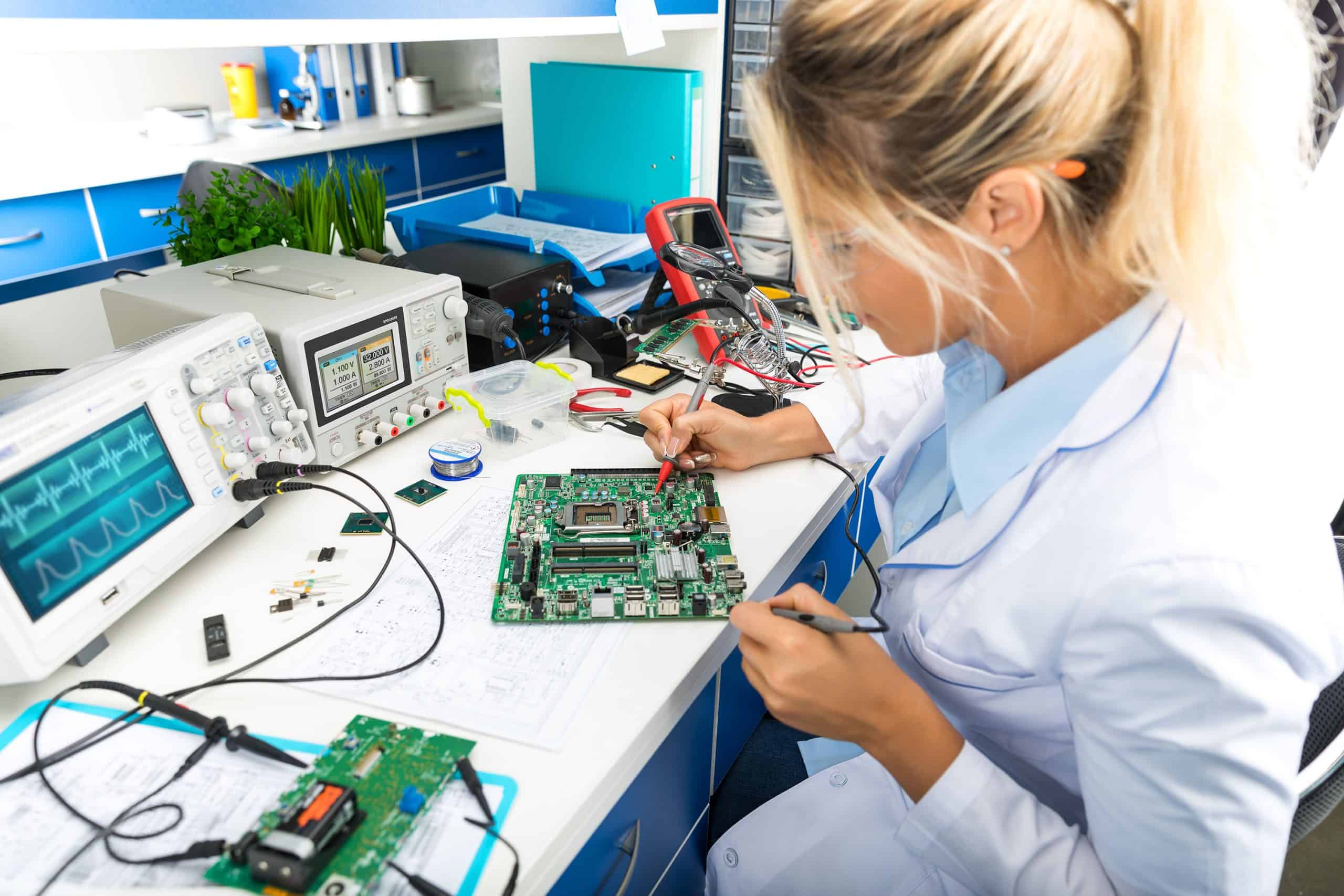
Here is a How to Test Electronic Components on a Circuit Board PDF for your conference. How-to-Test-Electronic-Components-on-a-Circuit-Board Download. How to Test Electronic Components With Multimeter. Testing electronic components with a multimeter is a fundamental skill in electronics troubleshooting and maintenance. Here's a general guide
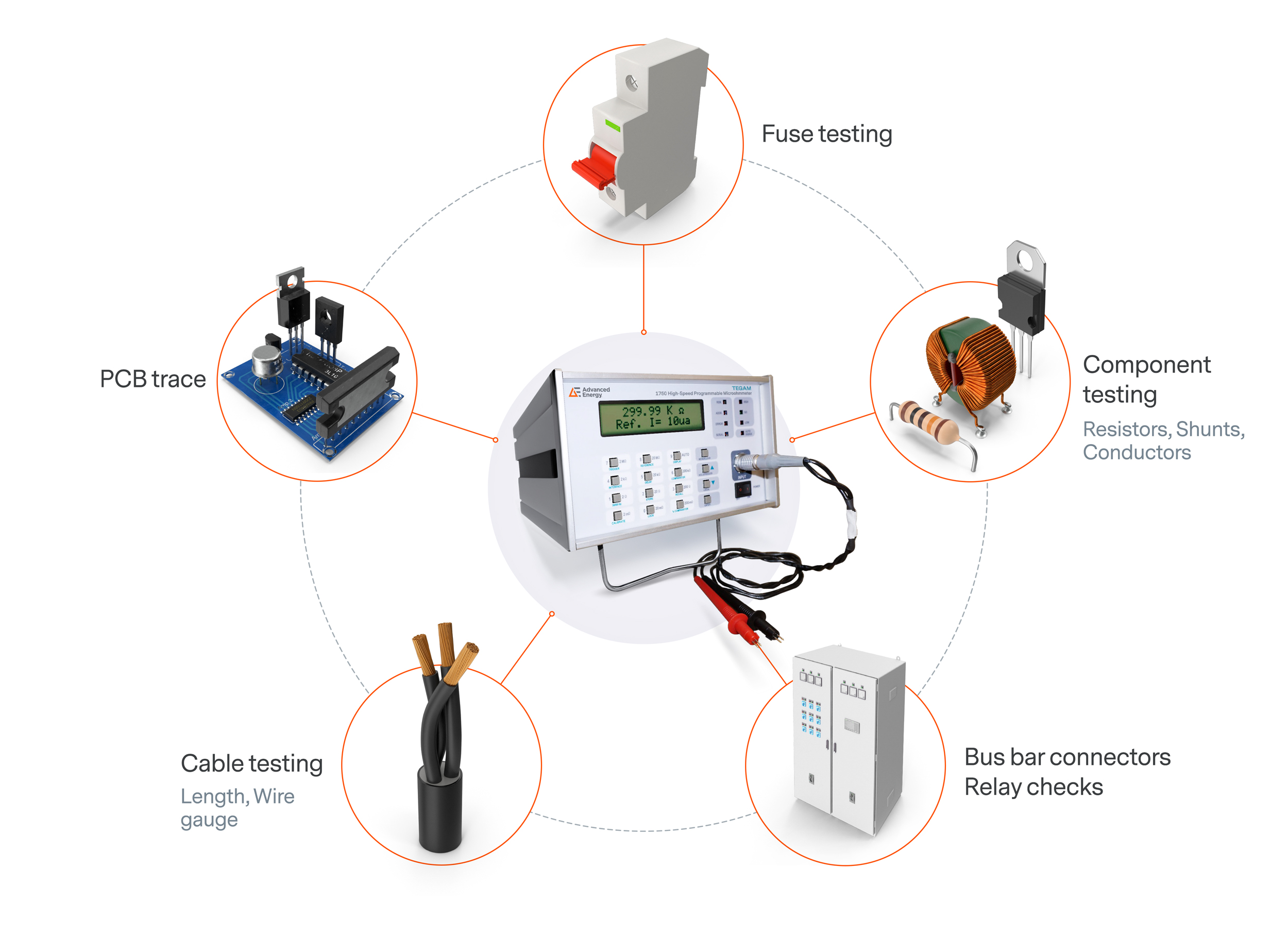
Testing electronic components is an essential step in the manufacturing process, as well as in troubleshooting and repairing electronic systems. This article aims to provide a comprehensive guide on how to test various electronic components, including resistors, capacitors, diodes, and transistors, using different techniques and methods.
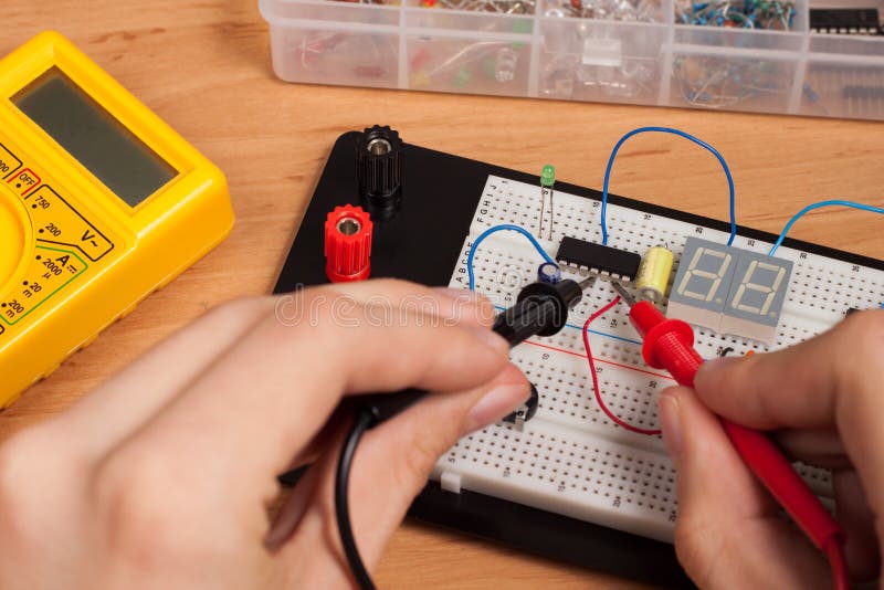
How to Test Electronic Components On a Circuit Board? Circuit Diagram
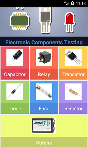
Explore different tutorials on Basic Electronics components like Resistor, Capacitor, Transistor, Diode, LED etc. Also explained how to use multimeter, how to test different types of capacitors, how to measure resistors accurately, how to identity PNP or NPN transistors, how to test MOSFET, how to test transformer using multimeter etc.. All tutorials explained in step by step and with To check electronic components, you typically use a multimeter or other specialized electronic testing equipment. The process of checking electronic components includes: Identify the component: Recognize the type of component you are testing (resistor, capacitor, diode, etc.). Learn how to use a multimeter to measure continuity, resistance, and voltage of various electrical components, such as batteries, cables, capacitors, diodes, fuses, LEDs, relays, resistors, switches, and transistors. Follow the basic instructions and safety tips for testing and troubleshooting devices with a multimeter.
Now let's get into how to use these tools to test various electronic components. 1. Resistor testing. A resistor is the most used electronic component. It is a two terminals device with the ability to resist the flow of current through it. Above is the circuit symbol and some real-time resistors. One thing to remember about resistors is, that
How To Test All Electronic Components with Multimeter Circuit Diagram
In this video, I have shown How to test all the basic electronics components like resistor, capacitor, diode, LED, transistor, fuse with a multimeter.As this